 On our last outing, we had to run the generator constantly so the kids could watch DVDs (the weather was foggy and cold). While the generator was quiet, I would rather not have to run it for hours on end just to watch TV. I'm sure my campsite neighbors would prefer I didn't run it either. So I decided to install an inverter. The inverter produces AC voltage from DC battery power. Now we can watch TV, brew coffee, etc., without running the generator.
The following is a technical description of how the installation went:
Step 1. Selecting the components for the inverter system
An inverter can be a wonderful convenience, but care has to be taken when considering the load it can place on the batteries. Choosing an inverter that both powers every AC appliance you want and does not drain the RV batteries too quickly is a tough balancing act.
My system will power a 27" TV and DVD/Surround system with powered subwoofer, a second 20" TV with DVD player, and a coffee pot. The following are the power consumption ratings for each appliance:
27" TV - 150 Watts
20" TV - 90 Watts
DVD/Surround System - 70 Watts
Powered Subwoofer - 100 Watts
Bedroom DVD - 30 Watts
Coffee Pot - 900 Watts
Adding all of these values up is more than what the inverter I chose can handle at once but I won't be using all of the appliances at the same time. I did it this way to both save the expense of a large inverter and keep the same battery bank I have for now (2 Deka Group 27 86 ampere hour) until the batteries require replacement. If I have to run the microwave, I'll just turn on the generator.
I also wanted an extra outlet in the kitchen area powered by the inverter for things like cell phone charging, walkie talkie charging, etc. so I installed a GFCI outlet which doubled as a power distribution point for the front and rear entertainment systems.
Here is the parts list with links to where I purchased them from:
Xantrex XPower Plus 1200 Inverter - $153.99
Xantrex XPower Remote Inverter Switch - $15.39
Iota 30 Amp Transfer Relay - $59
2 Inverter to Battery Cables - 3' of 2/0 AWG - $49
1 Class T 200 Amp Catastrophic Inverter Fuse - $49.95
1 GFCI Wall Outlet - $12.59
Miscellaneous hardware - ROMEX wiring, screws, electrical connectors, etc.
Step 2. Installing the Inverter and Remote Switch
For proper operation, the inverter must be mounted in a dry area with adequate ventilation, and as close to the batteries as possible to minimize the voltage drop from the batteries to the inverter. The inverter I chose can draw as much as 100 amps so keeping the battery cable length as short as possible is desired.
A word of caution though: never mount the inverter in the same compartment as the batteries unless you are using sealed AGM or Gel batteries. Flooded cell lead acid batteries can produce very flammable hydrogen gas when being charged and just switching on the inverter can cause a spark and possibly a subsequent explosion.
Before mounting the inverter, I had to mount the remote switch. I chose a location right next to the control panel for the LP level gauge, generator on/off switch, and holding tank level gauges (see Figure 1). Fishing the wiring down through the wall and under the bathroom tub was a little tricky but by doing so, I was able to drill a small hole through the floor right next to the compartment where the inverter was to be mounted. I routed the wiring into the compartment and connected to the inverter. This is necessary to do first as the connection is on the underside of the inverter and would not be possible to connect once the inverter was mounted.
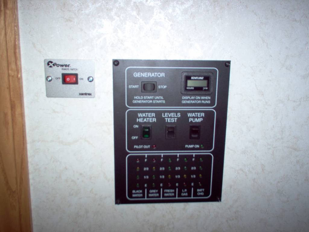
Figure 1. XPower Remote Inverter Switch
Now on to the inverter. I chose a compartment just to the rear of the battery tray on the driver's side of the motorhome. I mounted the inverter, and Class T fuse to the left compartment wall with the AC outlets facing to the outside (see Figure 2). I then cut a 1 1/2" hole in the side panel of the compartment and inserted a PVC electrical conduit flange into the hole. This was to prevent the battery cables, which pass through this hole to the batteries, from rubbing on the metal panel.

Figure 2. XPower 1200 Watt Inverter
Next, I wired, using very heavy 2/0 AWG welding cable, the positive connection from the inverter to the Class T fuse, then to the positive post on one of the batteries. Then I wired the negative connection from the inverter directly to the negative post of one of the batteries. Finally, I wired, using 6 AWG, the ground for the inverter to the chassis ground.
At this point, I did a quick test to see if the inverter was working correctly before proceding with the transfer relay and GFCI outlet wiring. I plugged in the 900 watt coffee pot directly into one of the inverter AC outlets, switched on the inverter, and then the coffee pot. Voila! The inverter bar meter read about 800 watts of power delivery and the coffee pot worked just fine.
Step 3. Wiring the Transfer Switch and GFCI Outlet
I wanted the ability to power the aforementioned applicances from shore/generator power when it is present instead of always from the inverter, saving battery power. In order to do this, a transfer switch is necessary to switch between the two sources of AC power. When the switch senses power from shore/generator power, it automatically switches the load from the inverter to the new power source.
One note: there are inverters that have built in transfer switches and are generally quite costly, but offer a convenient packaged solution. An example is the Prosine series of inverters from Xantrex. They also have a built in battery charger and are very good quality. I chose separates because I already have a high performance charger (Intellipower Progessive Dynamics PD9160 with Charge Wizard), and, well, I guess I'm cheap!
I decided to mount the transfer switch as close to power distrubution center (PDC) as possible so as to make wiring the easiest. Unfortunatley, there was not alot of space in the cabinet where the PDC was mounted, so wiring, while convenient, took some manuevering. I had about a 12" x 12" hole, after removing the PDC, to work within (see Figure 3)!
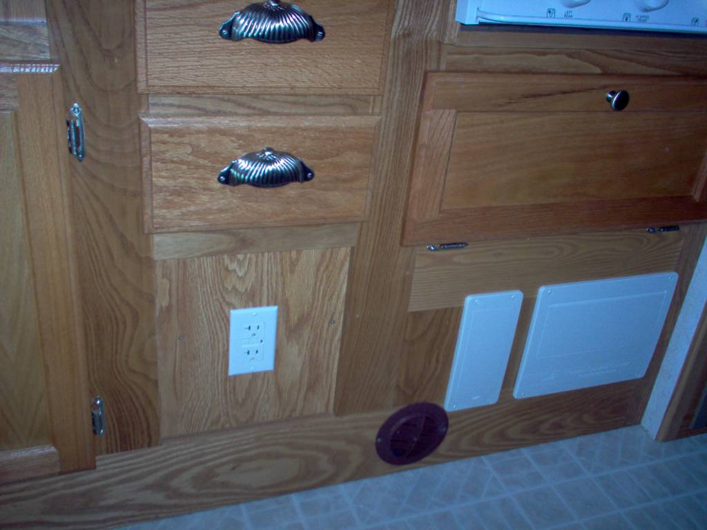
Figure 3. New GFCI Outlet
In the PDC, there were two 15 amp breakers, one for the front entertainment and one for the rear, that were consolidated into one 15 amp breaker, powering both entertainment systems and the new GFCI outlet. The other breaker was dedicated to the battery charger which had been wired into the rear circuit from the factory.
The "consolidated" breaker circuit was connected to the "alternate" connection points on the transfer switch. The wiring from the AC outlet from the inverter was connected to the "inverter" connection points on the transfer switch. Finally, the "output" of the transfer switch was connected to the GFCI outlet. (see Figure 4. - coming soon!). The "load" connection points on the GFCI outlet power the two entertainment systems. This arrangement made it possible to not have to wire in a sub-panel with separate breakers, making a clean, easily wirable solution.
I had to move the charger over a few inches to the left to make room for the rather large (8" x 8") transfer switch box, which was mounted after all of the wiring was completed. I mounted the GFCI outlet to the left of the PDC in an access panel for the water heater. Looks like it came from the factory that way!
Step 4. Testing the System
Before putting everything back together, it was test time. I plugged into shore power and switched the inverter on. I measured the voltage at the outlet and it was 120 VAC. So far so good. I then flipped the 50 amp breaker on in the PDC and I heard the transfer switch click over to new power source. I now had a reading of 118 VAC. So far so good.
Next was to turn on both entertainment systems and crank up the surround system. The power draw on the inverter meter was showing around 300 watts while all this was running. That's a 25 amp draw on the battery. At that rate of draw, I should get about 3 hours of run time before having to recharge the batteries. Of course, this isn't a normal situation as I would probably only have the front entertainment system on and not the rear.
Conclusion and Improvements
Overall, I'm very satisfied with the system but it could use a few improvements. Increasing battery capacity would be first on my list. The whole idea of the inverter was to minimize generator usage. Having to recharge the batteries with the generator after one pot of coffee and a movie is not what I had in mind. I will either add a third 12-volt Group 27 battery or replace the batteries with 2 high capacity 6-volt golf cart batteries.
The second improvement will be to replace the 15 amp breaker with a 20 amp breaker. There are a total of 4 AC wall outlets on the new GFCI circuit (including the GFCI outlet). The load terminals on the GFCI outlet can accommodate up to 20 amps of load while the GFCI outlet is rated for 15 amps. It would be nice to run a 1500 watt heater, the coffee pot, and the TV at the same time from this circuit, of course from shore/generator power as the inverter cannot provide that kind of power.
Part Manufacturers Links
Xantrex Technology Inc.
Iota Engineering
1 comment:
I like your inverter install, I kinda did the same thing, but wired a 1000 watt inverter into my bedroom circuit right out of the fuse panel. Those receptacles are always on inverter power. At night I can shut down the generator and then watch tv or a movie. I had a expensive Xantrex inverter charger setup, 25oo watt with auto transfer, but in reality really did not need it. I do miss the built in 130 amp battery charger though, I have two 45 amp Iota converters with the IQ smart charge controllers, works well and cost effective.
Post a Comment